Welcome to our guide on how to test a 5 Pin Relay using a wiring diagram. If you’re experiencing issues with your electrical system and suspect a faulty relay, it’s crucial to perform a thorough test to diagnose the problem accurately. By understanding the process of relay testing and utilizing a wiring diagram, you can ensure precise results and effectively troubleshoot any relay-related issues.
In this article, we will provide you with a step-by-step guide on testing a 5 pin relay, including the importance of relay testing, understanding 5 pin relays and wiring diagrams, and detailed instructions for each testing stage. With our comprehensive instructions, you’ll have the knowledge and confidence to successfully test a 5 pin relay and identify any malfunctions.
Before we proceed with the testing process, it’s important to have a basic understanding of 5 pin relays and how they are connected using wiring diagrams. In the next section, we will provide you with a thorough explanation of 5 pin relays and wiring diagrams to ensure a solid foundation for the testing process.
Understanding 5 Pin Relays and Wiring Diagrams
Before we dive into the testing process, let’s take a moment to understand the basics of 5 pin relays and how they are connected using wiring diagrams. Having this fundamental knowledge will help you navigate through the testing process with confidence.
5 pin relays are commonly used in automotive and industrial applications to control electrical circuits. They consist of five pins or terminals, each serving a specific function. Understanding the purpose and function of these pins is crucial for proper relay testing.
Wiring diagrams, on the other hand, provide a visual representation of how the different components in a circuit are connected. They show the interconnections between relays, switches, wires, and other electrical components. By referring to a wiring diagram, you can determine the correct terminal connections for a 5 pin relay.
Let’s take a closer look at the pins in a typical 5 pin relay and how they relate to the wiring diagram:
| Pin Number | Function |
|---|---|
| Pin 30 | Main power supply input |
| Pin 87 | Main power output |
| Pin 86 | Coil power input (positive) |
| Pin 85 | Coil power input (negative/ground) |
| Pin 87a | Additional power output (only present in certain relay designs) |
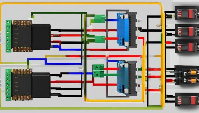
As shown in the above wiring diagram, the pins on a 5 pin relay are connected to different parts of the circuit, allowing the relay to control the flow of electrical current. By understanding these connections and referring to the wiring diagram specific to your application, you can accurately test a 5 pin relay and troubleshoot any potential issues.
Now that we have a solid foundation on 5 pin relays and wiring diagrams, let’s move on to the step-by-step guide for testing a 5 pin relay.
Step-by-Step Guide for Testing A 5 Pin Relay
Welcome to our step-by-step guide on how to test a 5 pin relay with a wiring diagram. Testing a relay is essential to ensure proper functionality and diagnose potential issues in your electrical system. By following these easy-to-understand steps, you’ll gain the knowledge and confidence to perform accurate tests and troubleshoot effectively.
The first step is to identify the relay terminals. Each terminal has a specific function, such as power, ground, and signal. Our guide will provide clear instructions on how to locate and distinguish these terminals, ensuring you can proceed with confidence.
Next, we’ll guide you through using the wiring diagram to connect the relay correctly. Wiring diagrams play a crucial role in understanding how the relay operates and establishing the necessary connections. With our detailed instructions, you’ll be able to navigate the diagram effortlessly and make the right connections for testing.
Once the wiring is complete, we’ll cover the process of measuring continuity and resistance. These measurements are crucial for evaluating the relay’s performance and identifying any faults. Our guide will explain the correct method of measuring continuity and resistance, enabling you to obtain accurate results and make informed decisions based on those readings.
Finally, we’ll explain how to interpret the test results accurately. Understanding what the test results indicate is essential for diagnosing problems and taking the appropriate action. With our clear explanations, you’ll be able to analyze the results confidently and determine the next steps to rectify any issues.
By following this step-by-step guide, you’ll acquire the necessary skills to successfully test a 5 pin relay using a wiring diagram. Whether you’re a beginner or have some experience in automotive electrical systems, our instructions will empower you to perform reliable tests and ensure the optimal functioning of your relay.
The post How To Test A 5 Pin Relay With Wiring Diagram first appeared on CollisionMax.
This post first appeared on Welcome To CollisionMax, An ABRA Company, please read the originial post: here

